3: Generating a mesh
Our simulations load script should load a finished .inp mesh file, so this tutorial will give one workflow about how to create these. (There are many ways; this is just one suggestion). We will use the open-source meshing tool Gmsh for this.
Create a .geo file
The first thing we need is to draw our geometry in a .geo file. Here is the square_bells.geo file. Notice that at the end, we put the different types of boundaries into Physical Curves, so that we can later tell our simulation which boundary corresponds to which boundary conditions.
SetFactory("OpenCASCADE");
lc = 0.06; // characteristic length; adjust as desired

Point(1) = {-0.115, -0.5, 0, lc};
Point(2) = {0.115, -0.5, 0, lc};
Point(3) = {0.115, -0.1, 0, lc};
Point(4) = {0.16, -0.1, 0, lc};
Point(5) = {0.16, -0.215, 0, lc};
Point(6) = {0.56, -0.215, 0, lc};
Point(7) = {0.56, 0.255, 0, lc};
Point(8) = {0.16, 0.255, 0, lc};
Point(9) = {0.16, 0.1, 0, lc};
Point(10) = {0.115, 0.1, 0, lc};
Point(11) = {0.115, 0.5, 0, lc};
Point(12) = {-0.115, 0.5, 0, lc};
Point(13) = {-0.115, 0.1, 0, lc};
Point(14) = {-0.16, 0.1, 0, lc};
Point(15) = {-0.16, 0.255, 0, lc};
Point(16) = {-0.56, 0.255, 0, lc};
Point(17) = {-0.56, -0.215, 0, lc};
Point(18) = {-0.16, -0.215, 0, lc};
Point(19) = {-0.16, -0.1, 0, lc};
Point(20) = {-0.115, -0.1, 0, lc};

Line(1) = {1, 2};
Line(2) = {2, 3};
Line(3) = {3, 4};
Line(4) = {4, 5};
Line(5) = {5, 6};
Line(6) = {6, 7};
Line(7) = {7, 8};
Line(8) = {8, 9};
Line(9) = {9, 10};
Line(10) = {10, 11};
Line(11) = {11, 12};
Line(12) = {12, 13};
Line(13) = {13, 14};
Line(14) = {14, 15};
Line(15) = {15, 16};
Line(16) = {16, 17};
Line(17) = {17, 18};
Line(18) = {18, 19};
Line(19) = {19, 20};
Line(20) = {20, 1};

Curve Loop(1) = {1, 2, 3, 4, 5, 6, 7, 8, 9, 10, 11, 12, 13, 14, 15, 16, 17, 18, 19, 20};
Plane Surface(1) = {1};

Physical Surface("domain") = {1};
Physical Curve("contact_bottom") = {1};
Physical Curve("contact_top") = {11};
Physical Curve("walls") = {2, 3, 4, 5, 6, 7, 8, 9, 10, 12, 13, 14, 15, 16, 17, 18, 19, 20};
Generate the mesh
Now that we have the .geo file, we need to turn it into a .inp mesh. It is important to only use quadrilateral elements, not triangles.
Julia itself has an interface for gmsh, Gmsh.jl. We can add it to the repo-root environment as follows:
import Pkg
Pkg.add("Gmsh")
Run the mesh script
Now we can use Gmsh.jl to load the .geo file, generate the 2D mesh, and write the Abaqus .inp file that Trixi can read. The repository keeps this in examples/mesh_generation/generate_square_bells_gmsh.jl, but the whole script is short:
import Gmsh: gmsh

const MESH_DIR = joinpath(@__DIR__, "..", "..", "assets", "square_bells")
const GEO_FILE = joinpath(MESH_DIR, "square_bells.geo")
const OUT_FILE = joinpath(MESH_DIR, "square_bells_gmsh.inp")

gmsh.initialize()

gmsh.option.setNumber("General.Terminal", 1)
gmsh.open(GEO_FILE)

# very important to "recombine" all triangles into quads, as Trixi needs quads
gmsh.option.setNumber("Mesh.Algorithm", 11) # Quasi-structured Quad
gmsh.option.setNumber("Mesh.RecombineAll", 1)
gmsh.option.setNumber("Mesh.SaveGroupsOfNodes", 1)
gmsh.model.mesh.generate(2)
gmsh.write(OUT_FILE)

gmsh.finalize()

println("Wrote ", OUT_FILE)
There are three details worth noticing. Mesh.Algorithm = 11 asks Gmsh for its quasi-structured quad algorithm. Mesh.RecombineAll asks Gmsh for quadrilateral elements instead of triangles. Mesh.SaveGroupsOfNodes writes the named boundary node sets into the .inp, which is how P4estMesh{2} can later match contact_bottom, contact_top, and walls to boundary conditions.
Run the script from the repository root:
julia --project=. examples/mesh_generation/generate_square_bells_gmsh.jlIt writes assets/square_bells/square_bells_gmsh.inp.
Use the mesh in a simulation
Keep mesh generation separate from the simulation. Once the mesh file exists, a simulation can load it with Trixi:
using Trixi

mesh_file = joinpath(@__DIR__, "..", "..", "assets", "square_bells", "square_bells_gmsh.inp")
mesh = P4estMesh{2}(mesh_file; polydeg=1,
                    boundary_symbols=[:contact_bottom, :contact_top, :walls])
The important contract is the set of physical group names. If the .geo file names a boundary contact_bottom, the simulation boundary-condition tuple should also use contact_bottom.
Visualize the mesh
Before using a generated mesh in a simulation, it is worth looking at it. The quickest way is to open the generated mesh directly in Gmsh before finalizing:
gmsh.fltk.run()You can put gmsh.fltk.run() after gmsh.model.mesh.generate(2) in the mesh-generation script if you want to inspect the mesh before writing it.
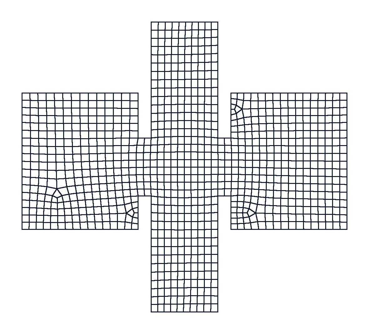
A rendered view of the generated mesh looks like this:
This page was generated using Literate.jl.